Digital TDI combines repeated images of the same moving surface after correcting their spatial alignment. In line-scan imaging, this allows several short exposures to contribute to one output line, increasing the useful signal without relying on a single long exposure. The correction is essential: each sensor row sees a particular feature at a different time, so the data must follow the motion of the object before it can be integrated.
For engineers working with conveyor inspection, continuous materials or precision scanning, digital time delay integration connects three decisions that are often considered separately: how the object moves, when the sensor acquires data and how those measurements are combined. Understanding that relationship helps determine whether TDI can improve defect visibility and what the camera, illumination and processing system need to support.
How Digital TDI Works
A conventional single-line camera records one narrow strip of an object at a time. Motion carries the next strip into view, and successive acquisitions build a two-dimensional image. A multiline sensor provides several rows along the direction of travel. A mark on the material passes through the field of view of each row in sequence, creating multiple observations of that same mark.
Digital TDI stores the observations, applies the required line delays and combines corresponding pixels. Integration takes place after the measurements have been digitized, commonly in an FPGA or another digital processing stage. The output represents aligned observations of one location on the object, rather than a mixture of neighboring locations.
The same principle can be implemented using overlapping area-scan acquisitions, provided the system captures the necessary repeated observations and registers them accurately. That approach requires suitable sensor readout, frame timing, memory and processing capacity. An ordinary area-scan camera does not become a digital TDI system simply by selecting a narrow region of interest.
Why Line-Scan Motion Correction Matters
Consider a dark scratch moving beneath four sensor rows. At one instant, the first row may be looking at the scratch while the remaining rows are looking at material farther along the conveyor. Adding those simultaneous readings directly would mix different parts of the surface and soften the feature. The processor instead combines readings captured when each row actually observed the scratch.
For steady motion, the delay depends on the spacing between rows, optical magnification and distance traveled between acquisitions. If neighboring active rows are separated by three projected row pitches and the image advances one pitch per trigger, their matching observations are three acquisition intervals apart. The correct delay therefore cannot be inferred from the number of active rows alone.
Some implementations support fractional-pixel registration or more advanced motion compensation. These capabilities must be checked for the selected design. A fixed integer line delay cannot automatically correct arbitrary vibration, sideways movement, rotation or changing magnification. Color line registration uses a related alignment principle, but aligning separate red, green and blue channels is not the same operation as summing repeated monochrome measurements.
Matching Line Rate to Object Speed
The required line rate follows from the object speed and the desired sampling distance along the direction of travel. Dividing speed in millimeters per second by millimeters per output line gives the line rate in lines per second. Across the web, sampling is set by the field of view and the number of active pixels; both directions need to be considered when setting the image aspect ratio.
As a calculated example, take material moving at 1,000 mm/s and a target sampling distance of 0.020 mm per line. The required line rate is 50,000 lines/s, or 50 kHz, giving a 20 µs line interval. With four adjacent stages, each separated by one projected sampling pitch, corresponding observations occur at 0, 20, 40 and 60 µs relative to the first observation.
If each stage uses a 5 µs exposure, the four measurements provide 20 µs of total exposure contribution. During each individual exposure the material travels 0.005 mm, equivalent to 0.25 output pixel in this example. These are design calculations, not measured camera performance. They illustrate why accumulated exposure, elapsed transit time and blur within an individual exposure are different quantities.
Encoder Synchronization and Changing Speed
A fixed line frequency produces constant spatial sampling only while the material speed remains constant. Encoder-based triggering can tie acquisition to distance traveled, keeping output lines evenly spaced as the conveyor accelerates or slows down. The trigger configuration must account for encoder resolution, any multiplication or division of pulses, and the camera’s supported trigger rate.
The encoder must also represent the movement of the inspected surface. Belt slip, roller eccentricity or motion between the material and its transport can leave registration errors even when the electrical timing looks correct. Camera alignment matters as well: a skewed sensor introduces motion across columns that a simple row delay does not remove.
Test the complete operating sequence, including startup, stops and direction changes. Buffered samples from before a stop or reversal may no longer belong to the same integration sequence. The implementation needs defined behavior for clearing or refilling those buffers and identifying valid output. At higher speeds, confirm that exposure and readout still fit within the available timing budget.
Digital TDI and Charge-Domain TDI
The main architectural distinction is where integration happens. Charge-domain TDI accumulates photocharge before the final readout. Digital TDI reads and digitizes the contributing observations before combining their values. Both require the integration process to follow the image motion, but their noise behavior and processing requirements differ.
For N equally exposed, accurately aligned digital measurements with independent random noise, summing increases the signal by N while the noise standard deviation increases by the square root of N. The resulting signal-to-noise improvement is therefore approximately the square root of N relative to one measurement. Four ideal measurements would provide about twice the signal-to-noise ratio, not four times.
Digital integration includes the read noise of each contributing measurement. Charge-domain accumulation can avoid repeated read-noise contributions and can therefore offer an advantage when signals are very weak. Real performance also depends on quantum efficiency, full-well capacity, illumination and calibration. Neither “CMOS” nor “TDI” alone tells an engineer which accumulation architecture a camera uses.
Summing, Averaging and Image Calibration
Summing aligned samples increases the output signal level. Averaging divides that sum by the number of samples, maintaining approximately the original brightness while reducing independent random noise. These operations can provide the same ideal signal-to-noise benefit before quantization and clipping, but they impose different requirements on output scaling and numerical range.
The accumulator needs enough precision to retain the result. For example, adding four unsigned 12-bit samples can produce 16,380, which requires 14 bits. Returning that result in a 12-bit output requires deliberate scaling or another defined mapping. Simply clipping the sum loses highlight information. TDI does not automatically create HDR imaging or increase the native full-well capacity of each contributing pixel.
Offset and gain differences between rows also need attention. Stable illumination, dark correction and flat-field calibration help ensure that the combined samples describe the surface consistently. Fixed-pattern errors do not necessarily average away like independent noise. Calibrate and assess the system in the actual acquisition mode, including its selected stages, exposure, gain and temperature conditions.
What Digital TDI Can and Cannot Correct
Digital TDI is most useful when repeated observations are available and the target remains sufficiently consistent while it crosses the integration region. Continuous paper, film, textiles and other moving surfaces are natural examples. Precision stages can also carry a stationary sample through a controlled scan. The benefit should be judged by whether the added signal makes the required feature easier to distinguish at the intended production speed.
Registration aligns separate observations; it does not by itself undo blur already recorded within each exposure. Excessively long exposures, optical defocus, saturation or missing acquisitions cannot be solved just by increasing the number of stages. Ordinary single-line data also cannot supply multiple independent exposures of a surface point if that point was captured only once.
Changes in object height, specular reflection or illumination can make successive observations differ for reasons other than motion. Combining them may reduce the contrast of a useful feature. Compare representative defects with integration enabled and disabled, at matched output brightness, so that a brighter display is not mistaken for better inspection performance.
Integrating Digital TDI into a KAYA Vision System
KAYA Vision’s custom camera and OEM development capabilities include area-scan and line-scan technologies with FPGA-based platforms. For a digital TDI project, the starting point is to define the sensing and correction requirements together: wavelength, field of view, smallest feature, motion profile, available light and required output format.
The location of processing affects the entire data path. Combining samples inside the camera can reduce the amount of raw data sent to the host. Processing externally provides access to the individual measurements, but the interface and memory must carry all of them. In a simple four-row arrangement with equal word sizes and acquisition rates, transferring four raw rows instead of one combined row requires roughly four times the pixel payload before protocol overhead.
Camera selection should therefore include usable readout modes, trigger behavior, row geometry and the required correction algorithm, alongside headline resolution and speed. Digital TDI support, stage count and compensation range should be confirmed for the proposed camera and firmware configuration. A high-speed interface alone does not establish those capabilities.
KAYA Camera Options for Motion-Imaging Projects
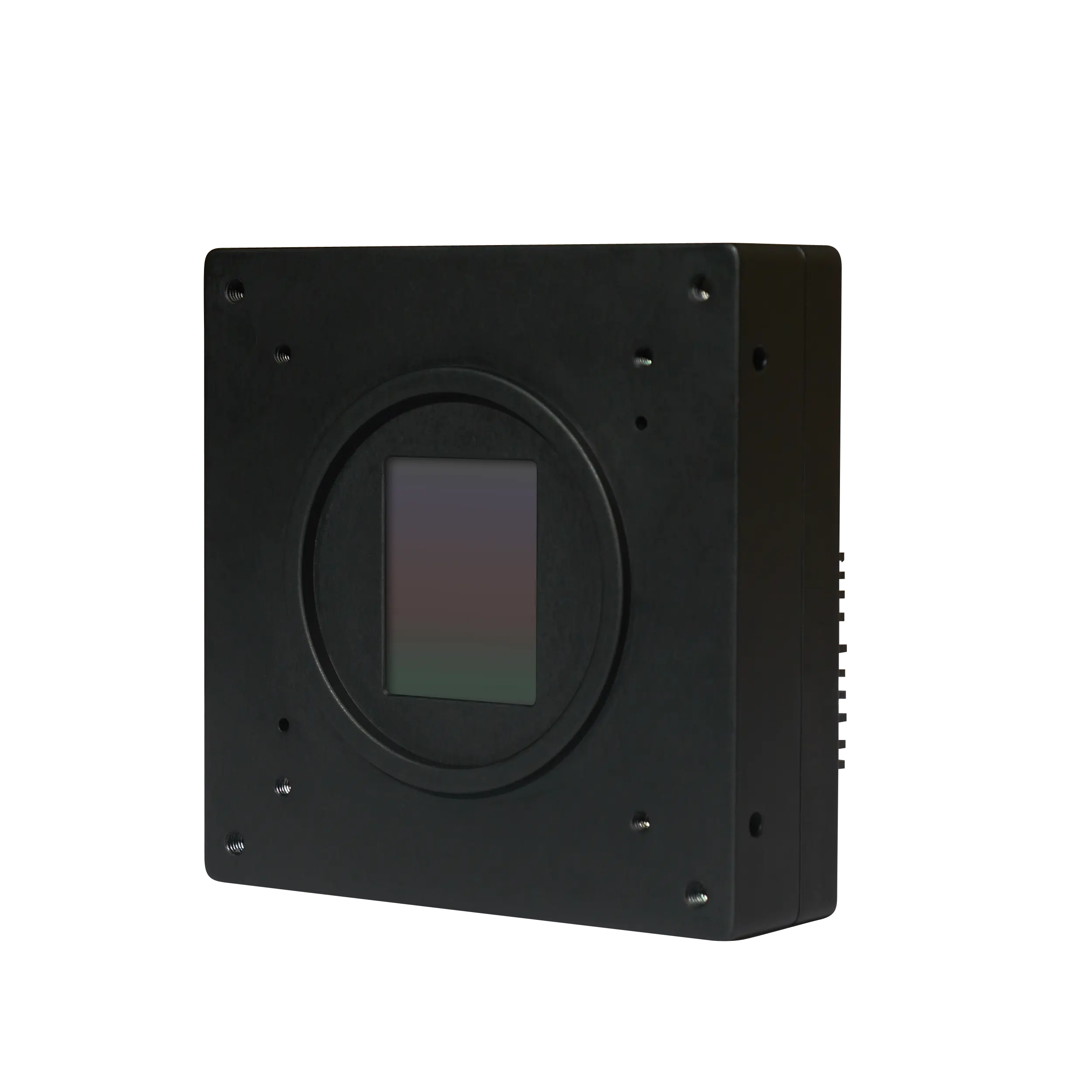
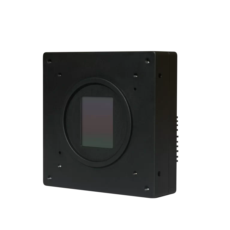
For a project using repeated area-scan observations, the Iron 5514 BSI provides a 4,608 × 3,072 global-shutter sensor with listed rates of 275 fps at 10 bits and 229 fps at 12 bits. Its short-exposure capability and image dimensions are inputs to the system design; the registration, buffering and integration process must still be specified for the application.
The Iron 0505 offers 5,120 × 5,120 pixels for applications that prioritize spatial sampling. Its High Speed version reaches 150 fps at 8-bit output and 145 fps at 10-bit output. Its listed 2.5 µs shortest exposure can be relevant when limiting movement within each observation, subject to obtaining sufficient optical signal.
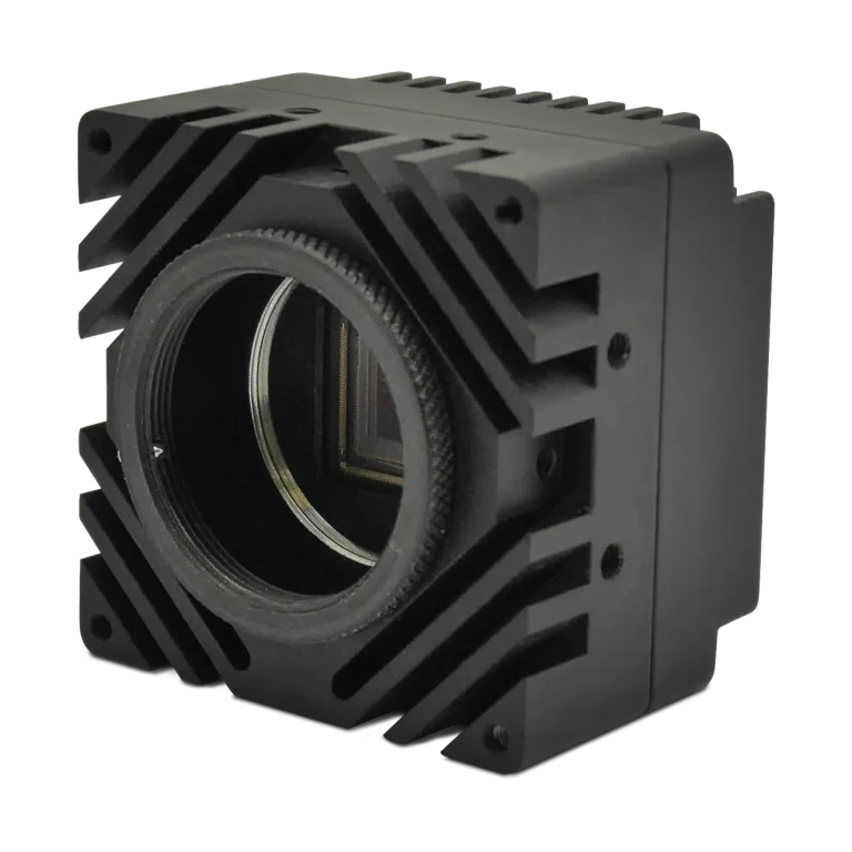
Where the scene requires faster temporal sampling, the Iron 4502 provides 2,048 × 1,216 pixels, with the current NS model specified at 1,430 fps at 8 bits. Its 10-bit and 12-bit modes have different maximum rates. These are area-scan cameras to evaluate within an imaging project, not a claim that the listed products include a standard digital TDI mode.

Before choosing hardware, compare line scan and area scan architectures at the required sampling scale. Then calculate the exposure time needed to limit motion blur within each individual measurement.
To discuss a line-scan or motion-compensated imaging project, contact KAYA Vision with the material speed range, desired object-space resolution and representative images or samples. These details provide a practical basis for evaluating the sensor, optics, synchronization and digital integration architecture.