The choice between line scan vs area scan cameras depends on how the surface is presented to the inspection system. A line-scan camera builds an image from narrow strips as the object or camera moves. An area-scan camera captures a rectangular field of view in each frame. Continuous webs often favor line scan, while separate parts, changing orientations and complete-object inspection often favor area scan.
The decision becomes clearer when resolution, coverage and motion are calculated together. A high megapixel count does not guarantee that every part of a moving surface will be inspected, and a high line rate does not guarantee enough light for the required detail. The architecture must satisfy both conditions before individual camera models are compared.
How Each Camera Builds an Image
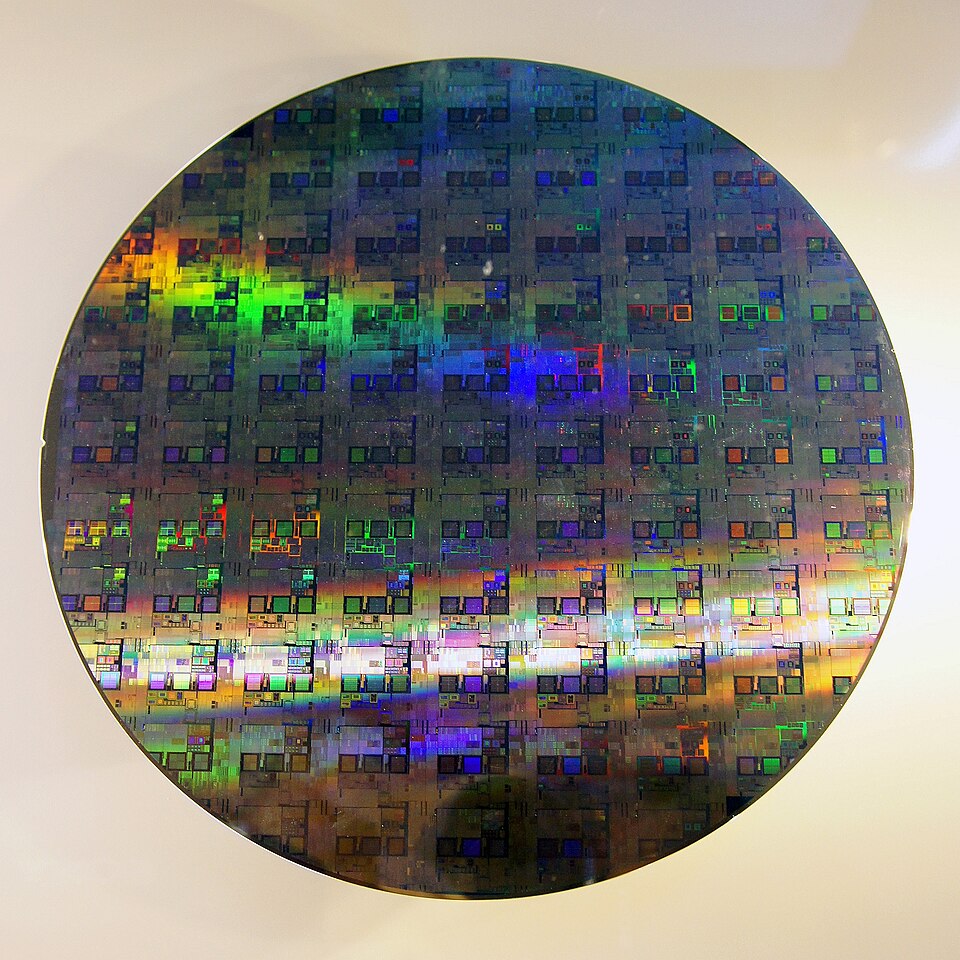
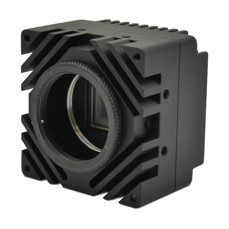
A line-scan sensor typically has one or several active pixel rows. Each acquisition records a strip across the object, and relative motion supplies the second image dimension. The completed image may represent a sheet several meters long, but its dimensions remain bounded by acquisition duration, memory and the processing system. Stable transport and correct line timing determine whether the reconstructed geometry is accurate.
An area-scan sensor contains a two-dimensional pixel array. It records the inspection region as a frame, making it straightforward to locate a part, evaluate several features or capture a changing event. Exposure behavior still depends on the shutter: a global shutter exposes the image together, whereas a rolling shutter exposes different rows at different times.
This distinction is separate from the interface. CoaXPress describes image transport and camera communication; it does not determine whether the sensor acquires lines or frames. The acquisition hardware and software must support the actual camera mode and data format.
When Line Scan Fits the Application
Line scan is a natural starting point for paper, film, metal strip, textiles and other continuous materials. A fixed inspection line can span the web while transport carries the surface through a controlled viewing and lighting region. A rotating cylinder can also present its circumference to a line-scan system, provided the rotation and sampling are coordinated.
The mechanics become part of the image formation process. Variations in speed change the distance represented by each line unless acquisition follows the movement. An encoder can maintain spatial sampling, but slip between the encoder mechanism and the inspected material still introduces errors. Web flutter, changing height and sideways movement also need to be considered.
Concentrating illumination onto a narrow strip can be useful, but the short time available for each line may still limit signal. Where repeated observations of the same surface are available, digital TDI and spatial correction can combine those observations. TDI adds alignment and integration requirements to the line-scan design.
When Area Scan Is the Better Starting Point
Area scan suits discrete products that fit within a defined inspection region: a connector, electronic assembly, package or machined component. One frame can preserve the spatial relationship between multiple features without relying on conveyor movement to construct the image. It is also useful when the target stops, rotates unpredictably or needs to be observed from several viewpoints.
Moving objects can be inspected with area-scan cameras when exposure is short enough and triggering places the object correctly in the field of view. A global shutter reduces distortion caused by different rows recording different moments. It still requires an appropriate exposure time to control blur.
Area scan can inspect continuous surfaces too. Successive frames need enough coverage and, when stitching or tracking requires it, overlap. The implementation must account for repeated pixels, motion between frames and any changes in lighting or perspective at the frame boundaries. The choice should follow these requirements rather than a blanket rule that conveyors always need line scan.
A Worked Comparison at the Same Sampling Scale
Consider a 100 mm inspection width sampled by 5,120 pixels. The object-space sampling is 100 / 5,120 = 0.01953 mm per pixel, or approximately 19.5 µm. A 0.1 mm feature spans about 5.1 pixels geometrically, although actual detectability also depends on contrast, optics and processing.
For an illustrative line-scan design using the same 5,120 samples across the width and square sampling along travel, a surface moving at 1,000 mm/s requires 51,200 lines/s. That follows from speed divided by the 0.01953 mm line spacing. The line interval is approximately 19.5 µs.
Now consider a 5,120 × 5,120 area-scan image covering 100 × 100 mm. With 10% overlap along travel, each frame advances coverage by 90 mm. At the same speed, continuous coverage requires at least 1,000 / 90 = 11.1 frames/s. This is a coverage calculation, not a statement that any exposure or optical setup will produce a useful image.
At 8 bits per monochrome pixel, the line-scan example produces approximately 262 MB/s of pixel data. The overlapping area-scan example produces about 291 MB/s. Both figures exclude transport overhead and host-side copies. This comparison shows why a large difference between line rate and frame rate does not necessarily imply a similarly large difference in bandwidth.
Exposure remains a separate calculation. At a 5 µs exposure the material travels 0.005 mm, or approximately 0.26 pixel at this scale. KAYA’s machine vision exposure time guide explains how to choose that limit for the feature being measured.
KAYA Area-Scan Cameras to Evaluate
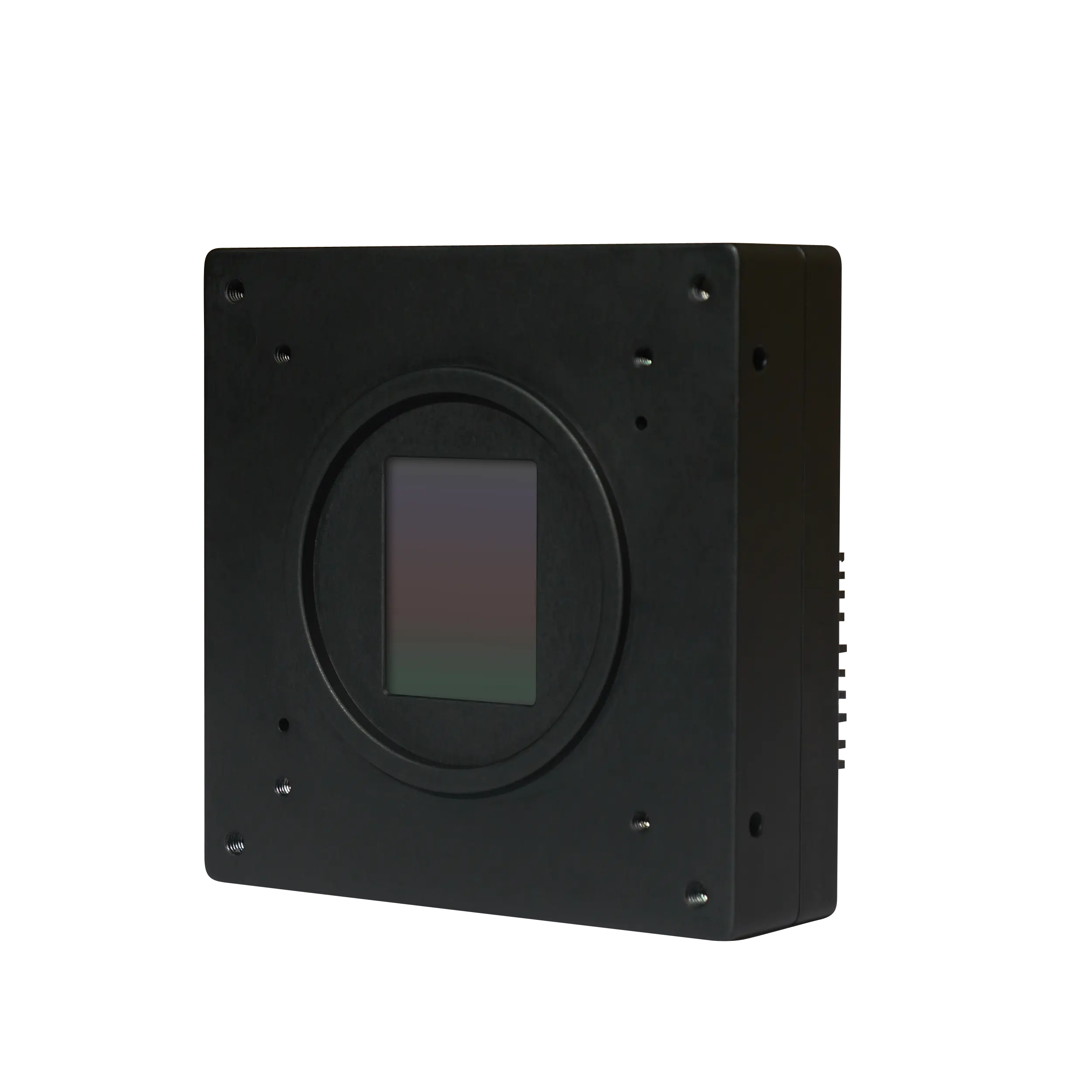
The Iron 0505 provides a 5,120 × 5,120 global-shutter sensor, matching the image dimensions used in the area-scan example. Its High Speed version is specified at up to 150 fps at 8-bit output and 145 fps at 10-bit output. The Normal Speed version is specified at 41 fps at 8, 10 and 12 bits. Version and bit depth therefore belong in the comparison, alongside resolution.
For applications balancing spatial detail with faster repeated acquisition, the Iron 5514 BSI offers a 4,608 × 3,072 global-shutter array. Its listed maximum rates are 275 fps at 10 bits and 229 fps at 12 bits. Its rectangular image shape creates a different field-of-view relationship from a square sensor, which matters when fitting a complete part or planning frame overlap.
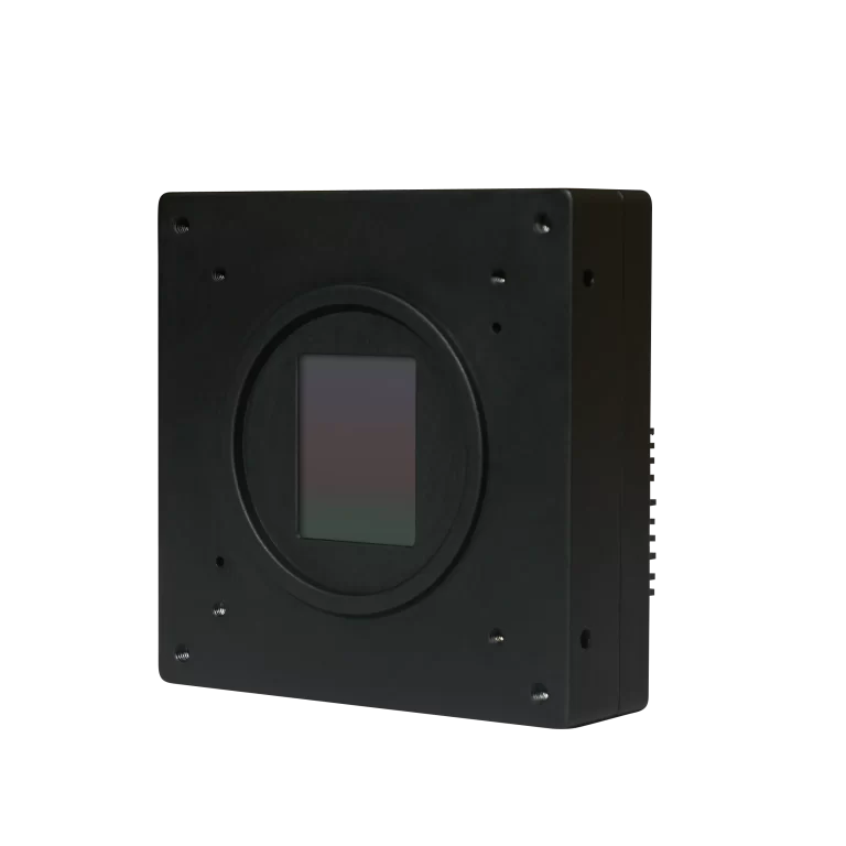
The Iron 4502 is another option when temporal sampling takes priority and 2,048 × 1,216 pixels cover the required features. The published NS model specification lists 1,430 fps at 8 bits, 1,169 fps at 10 bits and 847 fps at 12 bits. These are distinct operating modes, not interchangeable headline specifications.

These cameras are area-scan options. Their inclusion does not establish a standard line-scan or digital TDI mode. KAYA’s custom camera development covers area-scan and line-scan technologies and FPGA-based platforms, allowing the sensor and processing architecture to be evaluated for a specific OEM project.
Lighting, Optics and Host Processing
Line-scan optics must maintain image quality across the inspection line, while area-scan optics must cover the complete sensor field. In both cases, magnification, distortion and depth of field affect the relationship between pixels and the object. A wider sensor or smaller pixel does not remove the need to resolve the target feature optically.
Test lighting with representative good and defective samples. A scratch, coating variation or reflective edge may respond very differently to changes in angle and wavelength. Illumination that works well on a stationary sample must also deliver enough signal during the much shorter exposure used in production.
Finally, size the full data path. Check sustained camera output, frame-grabber capacity, host memory transfers, processing time and any recording requirement. A line-scan application may process image strips continuously; an area-scan application may process separate frames. Either can miss an inspection deadline if the software queues data faster than it can make decisions.
Can a Narrow Area-Scan ROI Replace a Line-Scan Camera?
A narrow region of interest can reduce transferred data and may increase acquisition rate, depending on sensor readout constraints. It does not automatically provide the timing, continuous line output, encoder behavior or integration stages of a dedicated line-scan design. Evaluate the achievable mode and its synchronization rather than assuming that a one-row ROI is equivalent.
Defining the Inspection Requirements with KAYA
A useful camera brief states the inspection width, smallest relevant feature, speed range, object motion, wavelength and available mounting space. Include whether every millimeter must be inspected, how missed or overlapping coverage will be handled and how quickly the result is needed. Those details make the line-scan versus area-scan decision concrete.
Contact KAYA Vision to evaluate the imaging architecture and suitable camera configurations. For applications that require repeated observations of a moving surface, the digital TDI guide provides the next step in understanding registration, synchronization and signal accumulation.