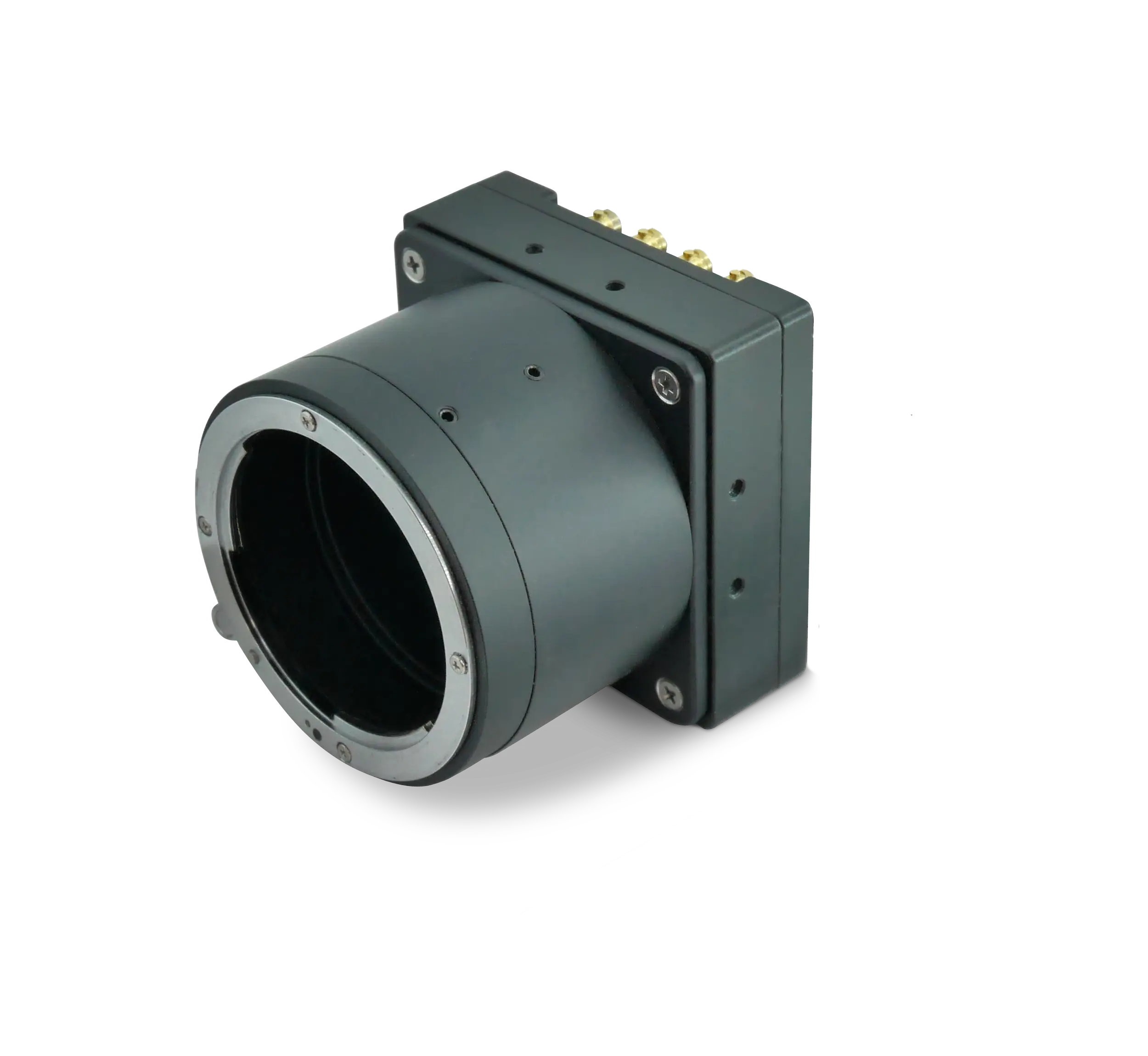
Precision coordinate measurement, surface inspection, and dimensional verification demand repeatable sub-micron accuracy. The imaging sensor you mount at the heart of your system therefore determines overall capability. This pixel-pitch / sensor-size guide focuses on the two most talked-about specifications and shows how they interact when you select a high-resolution metrology camera for demanding precision-measurement imaging workflows.
Why Pixel Pitch Comes First
Pixel pitch is the center-to-center spacing between adjacent pixels on the sensor. In the KAYA Vision Iron 661 and Zinc 661 PCIe cameras it is 3.45 µm, allowing each pixel to sample a very small portion of the scene. Smaller pitch means more pixels per millimeter of sensor, which directly raises the spatial sampling frequency. For a metrology engineer this translates to finer measurable detail and reduced interpolation error when fitting lines, circles, or edge positions.
However, shrinking the pixel pitch also reduces the amount of photon-collecting silicon area per pixel. If the aperture of the optical system and the illumination intensity remain constant, the signal-to-noise ratio falls. The Iron 661 counters that challenge with temporal noise below 2.7 e- and quantum efficiency above 63 % at 520 nm, keeping the noise floor low enough for precise edge repeatability. Zinc 661 PCIe shares the same sensor and brings identical low-noise performance to PCIe-based systems.
Sensor Size Sets the Field of View
While pixel pitch defines sampling density, sensor size dictates how many of those pixels you get and how wide an area you can inspect at once. The 56.7 mm diagonal of the Sony IMX661 sensor used in both the Iron 661 and Zinc 661 PCIe provides 13 400 × 9 528 pixels—just under 128 megapixels. Combine that resolution with the 3.45 µm pitch and you achieve two key goals simultaneously: enormous detail and a field of view large enough for 300 mm wafers, automotive body panels, or TFT masks.
The temptation may be to choose an even larger sensor, but you must balance four interrelated constraints:
- Lens image circle: your optics must uniformly illuminate the whole active area.
- System size: larger sensors often require larger, more expensive telecentric lenses.
- Lighting uniformity: greater field size demands tighter control of irradiance across the scene.
- Data-interface bandwidth: more pixels mean more bytes; PCIe Gen 3 in Zinc 661 PCIe or CoaXPress 2.1 in Iron 661 are essential to move the data at full speed.
The Trade-Off Diagram
Visualize pixel pitch on the X-axis and sensor diagonal on the Y-axis. Moving left—smaller pitch—raises resolution but lowers full-well capacity and dynamic range. Moving up—larger sensor—expands field but increases system cost. The sweet spot for a high-resolution metrology camera is the upper-left corner where both factors are optimized. Iron 661 and Zinc 661 PCIe occupy precisely that quadrant: more than 70.8 dB dynamic range and 9 825 e- full-well capacity at 3.45 µm, paired with a 3.6″ sensor format.
Calculating Real-World Measurement Accuracy
Actual system precision is determined by effective pixel size on the object plane. Use the simple formula:
Effective Pitch = (pixel pitch / magnification)
For instance, if you run an Iron 661 in a 1:1 telecentric setup, your effective pitch remains 3.45 µm—perfect for PCB trace-gap measurement. Apply a 0.5× telecentric lens and your effective pitch doubles to 6.9 µm, still tight enough for dimensional checks on consumer-electronics housings but with double the field of view.
The quantitative relationship between measurement repeatability (σ) and effective pitch (p) often follows σ ≈ p⁄3 for high-contrast edges. Therefore dropping from 6.9 µm to 3.45 µm can cut repeatability error from roughly 2.3 µm to 1.15 µm—an easy win simply by selecting the finer-pitch sensor.
Metrology-Focused Capability of Zinc 661 PCIe
Zinc 661 PCIe targets machine builders who prefer direct, frame-grabber-less streaming through a PCIe Gen 3 edge connector. You obtain up to 21.5 fps at the full 128 MP resolution—more than adequate for in-station static measurement or slow-moving XYZ stages. Trigger inputs, four timers, and four counters let you synchronize exposure to laser-displacement sensors, encoders, or index tables. Because the camera card resides inside the PC enclosure, cabling is minimal and immune to EMI, which is crucial when you operate micrometer-resolution linear stages.
The global shutter eliminates motion blur if a part vibrates or a gantry is settling. With a shortest exposure of 10 µs the Zinc 661 produces crisp edges even under strobed LED line lights. Metrology integrators benefit from the GenICam API that enables deterministic control over exposure, gain, and region of interest from common software packages such as Halcon or VisionPro.
High-Speed Measurement with Iron 661
Some dimensional-gauging tasks require higher throughput: battery-cell tab inspection, large-sheet flatness measurement, or multi-view robotic gauging. Iron 661 addresses those needs with CoaXPress 2.1 running on four CXP-12 links for an effective 40 Gbps data stream. That bandwidth delivers a 128 MP frame every 46 ms (21.5 fps), supporting 100 % in-line measurement on moving conveyors.
Power over CoaXPress simplifies cable routing through cable chains and robot arms, while the <14 W power draw keeps thermal drift negligible. Edge repeatability remains stable during long shifts thanks to the camera’s active sensor alignment and MIL-STD-810G shock/vibration qualification.
Lens Selection Considerations
Once you choose the sensor, your lens must resolve the necessary line pairs per millimeter. For a 3.45 µm pitch, the Nyquist frequency is roughly 145 lp/mm. Select telecentric optics specified for at least that value across the full 56.7 mm image circle. For sensors of this size you typically move to an M72 mount, the native mount supplied on both Iron 661 and Zinc 661 PCIe.
Keep working distance in mind: shorter distance maximizes numerical aperture, improving modulation transfer at high spatial frequencies. This directly sharpens the grey-level slope across edges, which in turn enhances sub-pixel edge-localization accuracy.
Lighting Geometry and Dynamic Range
Metrology scenes often combine shiny metal and dark machined recesses, demanding wide dynamic range. Iron 661 and Zinc 661 PCIe both exceed 70 dB, but you can extend usable range with properly designed lighting:
- Use diffused dome or cloud illumination to minimize specular hotspots.
- Add polarized ring lights and analyze crossed-polarization images to emphasize surface scratches.
- Employ HDR acquisition via multiple exposures if surface-reflectivity span exceeds 1 000:1.
The cameras’ on-board look-up tables and defect-pixel correction ensure linear, artifact-free intensity ramps—vital for accurate threshold-based edge detection.
Environmental Stability
Temperature drift translates into measurement drift. The Iron 661 and Zinc 661 PCIe operating ranges of 0 °C to 50 °C for commercial versions and −40 °C to 70 °C for industrial versions cover virtually every shop-floor scenario. For nanometer-level repeatability mount the camera to an Invar plate and allow a short warm-up to reach equilibrium.
Checklist for Camera Selection
- Specify required measurement repeatability and back-calculate effective pixel pitch.
- Choose sensor pitch that supports that value under realistic lens magnification.
- Ensure sensor diagonal fits your desired field of view with available optics.
- Verify dynamic range and noise specifications at your target exposure time.
- Confirm data interface—PCIe or CoaXPress—matches throughput and distance needs.
- Plan mechanical mount, lens, and environmental control simultaneously.
- Select firmware features such as ROI or LUT that reduce downstream processing load.
Putting It All Together
By systematically balancing pixel pitch and sensor size you transform an abstract data sheet into a concrete specification for your precision-measurement imaging station. The KAYA Vision Iron 661 and Zinc 661 PCIe cameras illustrate how leading-edge 3.45 µm pixels on a large 3.6″ sensor provide an ideal foundation for next-generation high-resolution metrology systems. Apply the principles outlined here and your gauge repeatability and reproducibility (GR&R) scores will reflect the true capability of your process rather than the limitations of your imaging chain.


